Calibrated wideband measurements on a modified VNA for modulated-input control and linearization of a multi-port PA
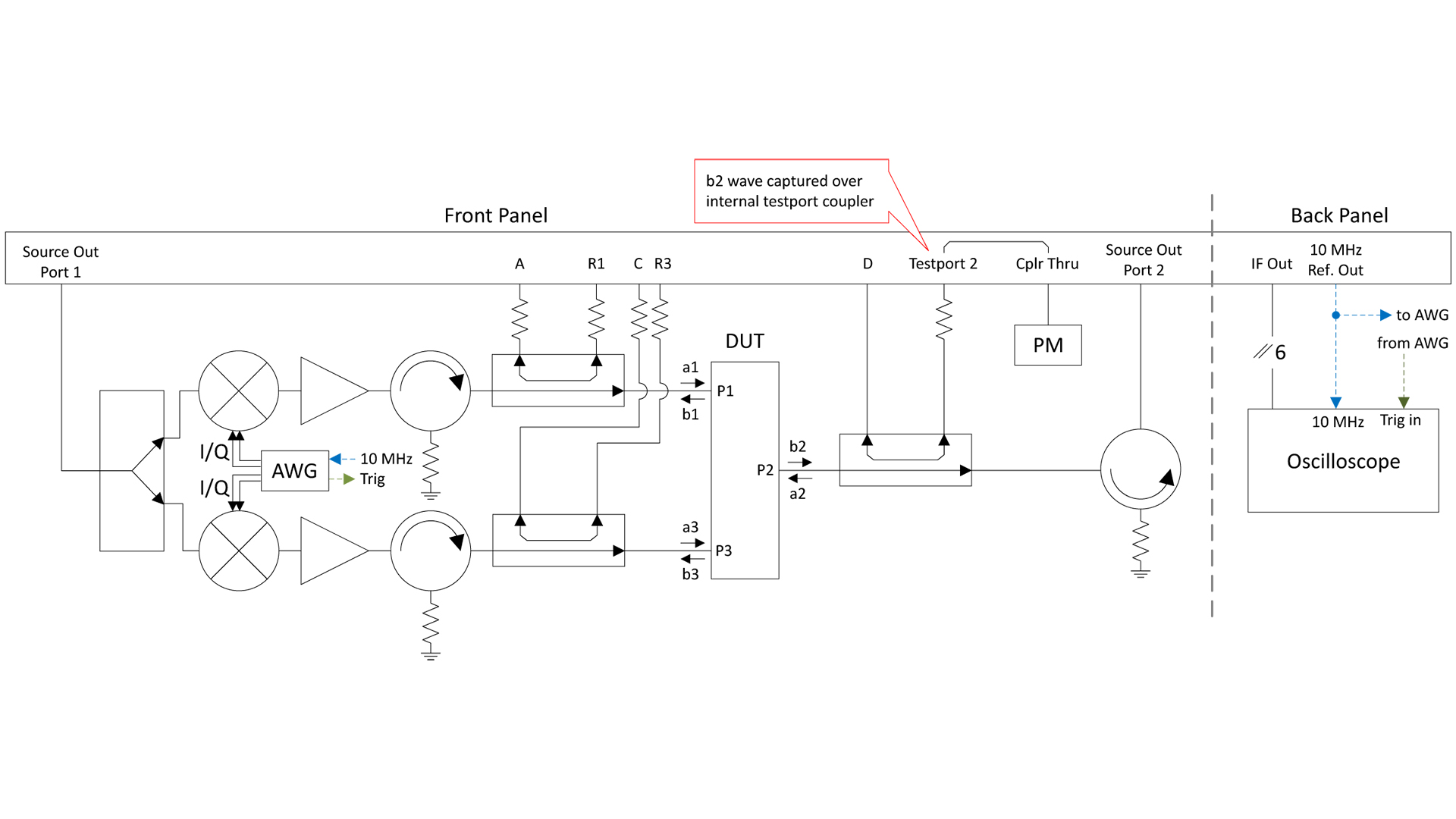
Fig. 1: Block diagram of the three-port wideband measurement system based on the modified PNA-X
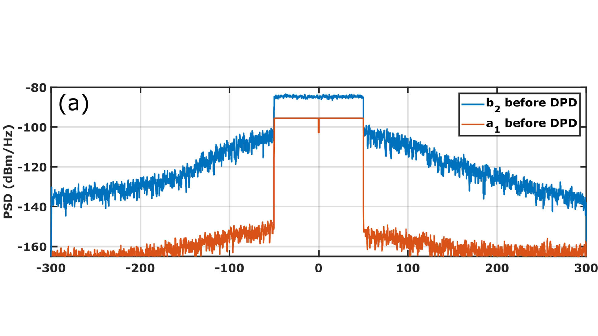
Fig. 2: Spectra of DIDPA waves before linearization
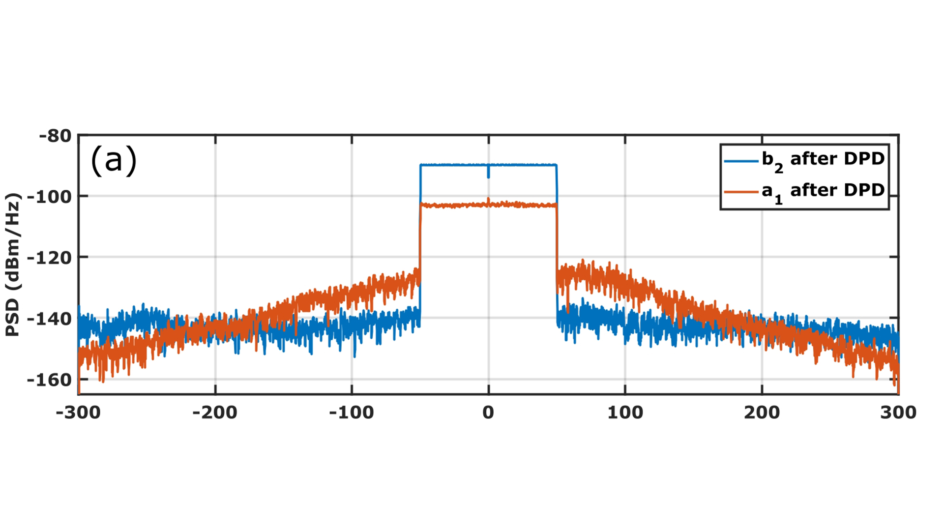
Fig. 3: Spectra of DIDPA waves after linearization
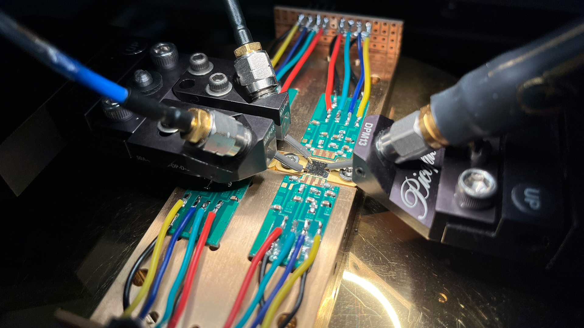
Fig. 4: Photo of the two-stage dual input Doherty PA MMIC for digital synthesis of the optimum electrical conditions realized by a passive quadrature hybrid at the input of the DIDPA.
In modern telecommunication systems it is essential to characterize circuits and amplifiers with wideband modulated signals in calibrated reference planes. Furthermore, novel systems are often based on multiple input systems like Doherty or voltage supply modulation to allow large dynamics and high-power back-off efficiency. To characterize such a multiple-input device, we extended the unique large-signal wideband (WB) measurement system shown in [1] to three ports for modulated-signal control and optimization of a dual-input Doherty power amplifier (DIDPA). The device-under-test (DUT) utilizes a two-stage amplification at a center frequency of 24 GHz without any input hardware splitting to impose a user-defined emulated splitting ratio [2].
To enable an independent control of the main and auxiliary PA, we added two separate IQ mixers in front of the DUT which are sharing a common local-oscillator (LO) signal provided by the PNA-X. A 4-channel arbitrary waveform generator (AWG) generates the baseband I and Q signals and also provides a trigger for wideband measurements. For each branch, a pre-amplifier is mandatory to achieve the requested power at the DUT input. Furthermore, the setup requires isolators for pre-amplifier protection and improved source match as well as external couplers. The full block diagram of the setup is shown in Fig. 1. The modified PNA-X is equipped with internal WB downconversion mixers exceeding a bandwidth (BW) of 5 GHz. For external capturing of the incident and reflected power waves of the downconverted signals, we used an 8-channel Keysight MXR oscilloscope. Six of the available channels are connected to the PNA-X testport and reference receivers, one channel is used for triggering the oscilloscope in order to improve the dynamic range based on coherent averaging.
The three-port setup requires a new calibration routine. We used a stepped continuous wave (CW) signal [1] in a frequency range between 23.7 GHz and 24.3 GHz to ensure a very precise error term calculation and high dynamic range. In dependence of the number of calibrated frequency bins, this procedure is very time consuming for a SOLT (short, open, load, thru) calibration of three ports including capturing and signal processing. Therefore, we used the AWG to generate a 600 MHz Schroeder-phased multisine signal with 301 tones, centered around 24 GHz, to perform a wideband SOLT calibration in forward direction of port 1 and port 3. We interpolated signal components which are not landing on the calibrated frequency bins over intermediate bins. For each tone, the error terms can be calculated separately as in [1] and used for error correcting the signals to the reference planes. With this method, we only need to measure once for each calibration standard. The calibration time strongly decreases, which is a key enabler for future measurements up to 16 ports.
We used the calibrated setup for the digital synthesis of the electrical conditions realized by a passive quadrature hybrid at the input of the DIDPA at wideband excitation [2]. The splitting ratio and phase between the main and auxiliary branch covering a BW of 100 MHz was of interest to optimize the DUT. Due to non-linearities from the pre-amplifiers in the signal path, we used an iterative-learning-control (ILC) scheme with an outer and inner loop for linearization and setting the desired splitting condition. The outer ILC loop is mainly targeting the desired output signal of interest at the main branch of the DIDPA, which is for linearization. For each iteration, an inner ILC loop was setting the correct splitting conditions between the branches of the DIDPA. To determine the best values for splitting ratio and phase for a maximum output power and PAE of the DIDPA, we first conducted preliminary sweeps of both variables with CW excitation. To characterize the DUT, we used a 1000-tone, 100 MHz BW random phased multitone signal to emulate modern 5G signals. Fig. 2 shows the wideband a1 and b2 waves before linearization, resulting in an ACPR = -21.2 dB and EVM = -15.7 dB where Fig. 3 corresponds to the measured waves after linearization. We achieved an improvement of 27.6 dB in ACPR and 28 dB in EVM at a maximum output power of 29.3 dBm using the developed algorithm.
In the future, the setup will be extended for multi-port measurements up to 16 ports. A possible use case is to emulate the complex interaction in integrated MIMO transmitter systems with beam steering, where one amplifier alters the performance of the neighboring amplifier. For such a high number of ports, advanced and fast calibration routines as shown are mandatory. This work was conducted in cooperation with University Bologna and is a great example for international collaboration and possibilities for the future. It was partly funded by the German Federal Ministry of Education and Research (BMBF) under the project reference 16FMD01 (Forschungsfabrik Mikroelektronik Deutschland – FMD).
Publications
[1] C. Schulze, W. Heinrich, J. Dunsmore, and O. Bengtsson, „Wideband Vector Corrected Measurements on a Modified Vector Network Analyzer (VNA) System,” in Proc. ARFTG Microw. Meas. Conf., 2022, pp. 1-4.
[2] M. Mengozzi, G. P. Gibiino, A. M. Angelotti, C. Florian, A. Santarelli, C. Schulze, O. Bengtsson, “Modulated-Input Control and Linearization of a Multi-Port Millimeter-Wave PA by VNA-based Calibrated Wideband Measurements,” presented at ARFTG Microw. Meas. Conf. 2023.