Wideband vector-corrected measurements on a modified vector network analyzer system for 5G-MIMO and space applications
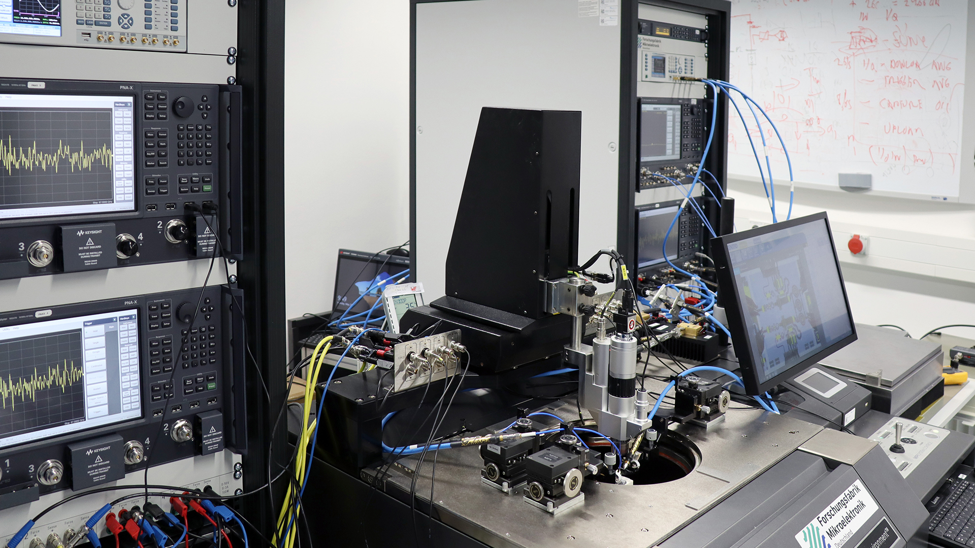
Unique measurement system for 5G-MIMO and space applications.
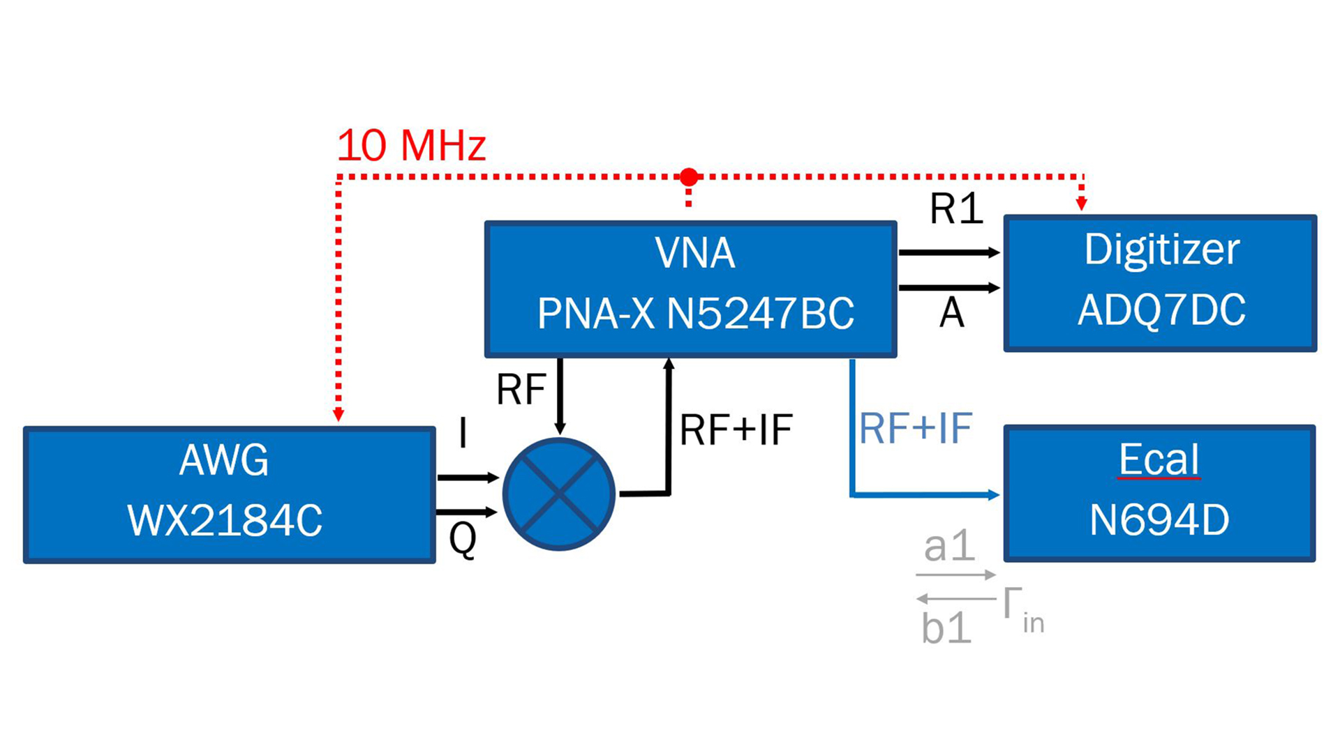
Fig. 1: Block diagram of the wideband measurement system.
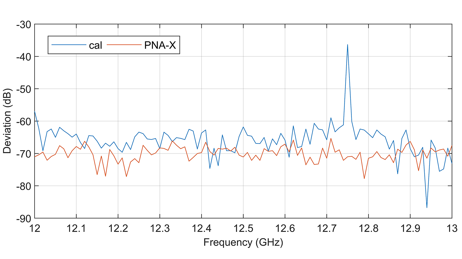
Fig. 2: Deviation between traceable Ecal impedance, error corrected measurements (blue) and PNA-X performed calibration (red).
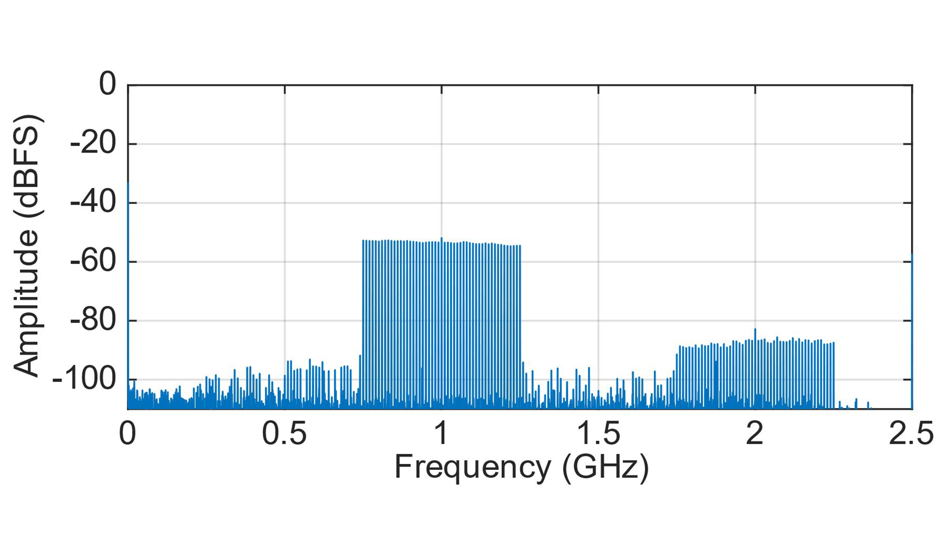
Fig. 3: DFT of the downconverted Schroeder phased multisine signal with 51 tones and 500 MHz bandwidth, captured at receiver R1.
In modern telecommunication systems, there is an increasing need to characterize components and circuits with defined wideband (WB) signals in calibrated reference planes. With the unique 5G-MIMO measurement system and its modified vector network analyzers from Keysight Technologies, FBH is now able to measure devices under test (DUT) up to 67 GHz with an instantaneous bandwidth exceeding 2 GHz without the need of frequency stitching or other complex techniques for extended bandwidth analysis.
The first step was to develop a combined radio frequency (RF) and intermediate frequency (IF) calibration procedure for only one port of the modified PNA-X with BC option, which contains WB downconversion mixers and additional IF couplers for IF capturing over a bandwidth of 5 GHz. The PNA-X in this setup provides the local oscillator (LO) for the external IQ mixer and is responsible for the downconversion. The baseband signal was generated with an external 14-bit arbitrary waveform generator (AWG), and the downconverted signals of receiver R1 (the incident wave) and receiver A (the reflected wave) were captured externally with a 14-bit digitizer at the additional IF outputs of the PNA-X, which is shown in Fig. 1. A Keysight Ecal module was connected to the reference plane for calibration and validation.
The calibration in this example was done with a swept continuous wave (CW) signal from 12 GHz to 13 GHz at 101 points. The frequency of the PNA-X LO was set to an offset of 500 MHz, which is necessary to avoid an overlap of the second harmonic with the signal band of interest and depends on the bandwidth of the WB captured signal. Therefore, an RF of 12 GHz corresponds to an IF of 500 MHz. In addition, the dynamic range of the calibration signal was improved by averaging to achieve a signal-to-noise (SNR) ratio of better than 80 dB. The connected Ecal module offers different known impedances and three of them were representing non-ideal open, short and load terminations at the reference plane. The downconverted incident and reflected waves for each frequency point and calibration standard were measured with the digitizer to calculate the measured input reflection coefficient. In combination with the known traceable input reflection coefficients of the Ecal module, it was possible to calculate the directivity, reflection tracking and source match error terms of the system up to the calibrated reference plane of the port. For verification of the error terms, the Ecal module was set to a fourth impedance state, which was not considered during the calibration. It was measured and vector corrected to the reference plane with the previously found error terms. In addition, a second calibration was done with the internal PNA-X calibration routine at identical settings for comparison. The deviation between the traceable impedance of the Ecal module and the error-corrected measurement of the CW calibration routine as well as the PNA-X internal calibration routine are shown in Fig. 2. The deviation between the error-corrected measurement and the known traceable impedance of the Ecal module is less than -59 dB over the full bandwidth, which is comparable to the PNA-X performed calibration. The large deviation at 12.75 GHz is due to an interleaving error of the external ADC at an IF of 1.25 GHz.
Afterward, the wideband capability of the calibrated system was tested. To obtain a multisine signal with an optimum SNR and a low crest factor, a Schroeder phased multisine baseband signal with a bandwidth of 500 MHz and a tonespacing of 10 MHz was generated. The signal was centered around an RF at 12.5 GHz to ensure that each tone is falling into a calibrated frequency bin. Fig. 3 shows the discrete Fourier transform (DFT) of the downconverted wideband signal at receiver R1, with the Ecal module connected at the reference plane. For error correction and validation, the Ecal module was again set to the fourth impedance state and measured with the digitizer. Each tone was error corrected to the reference plane with the previously determined error terms to calculate the deviation between the traceable input reflection coefficient and the error corrected input reflection coefficient of the wideband signal. The measurement showed very good accuracy in the range of -50 dB.
In the future, the wideband calibration method will be extended to multi-port measurements with eliminated ADC interleaving spurs. For upcoming wideband MIMO measurements, this is a key enabler. Further information on the capability of the system can be found in this press release: Unique measurement system for 5G-MIMO and space applications
This work was partly funded by the German Federal Ministry of Education and Research (BMBF) under the project reference 16FMD01 (Forschungsfabrik Mikroelektronik Deutschland).
Publication
C. Schulze, W. Heinrich, J. Dunsmore, and O. Bengtsson "Wideband Vector Corrected Measurements on a Modified Vector Network Analyzer (VNA) System" presented at the 99th Automatic Radio Frequency Techniques Group, ARFTG, (2022).