An innovative integrated reconfigurable capacitor cell for multiband operation

Fig. 1. Schematic of the reconfigurable capacitor bank. It consists of two switch-capacitor branches in parallel, connected to a common RF port. Isolation resistors are added at the input to suppress possible oscillations.
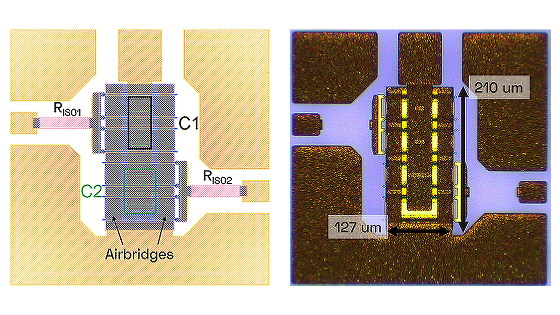
Fig. 2. Layout (left) and photo (right) of the reconfigurable capacitor cell. The gate resistors are not visible in the photo, since they are on a lower layer covered by passivation.
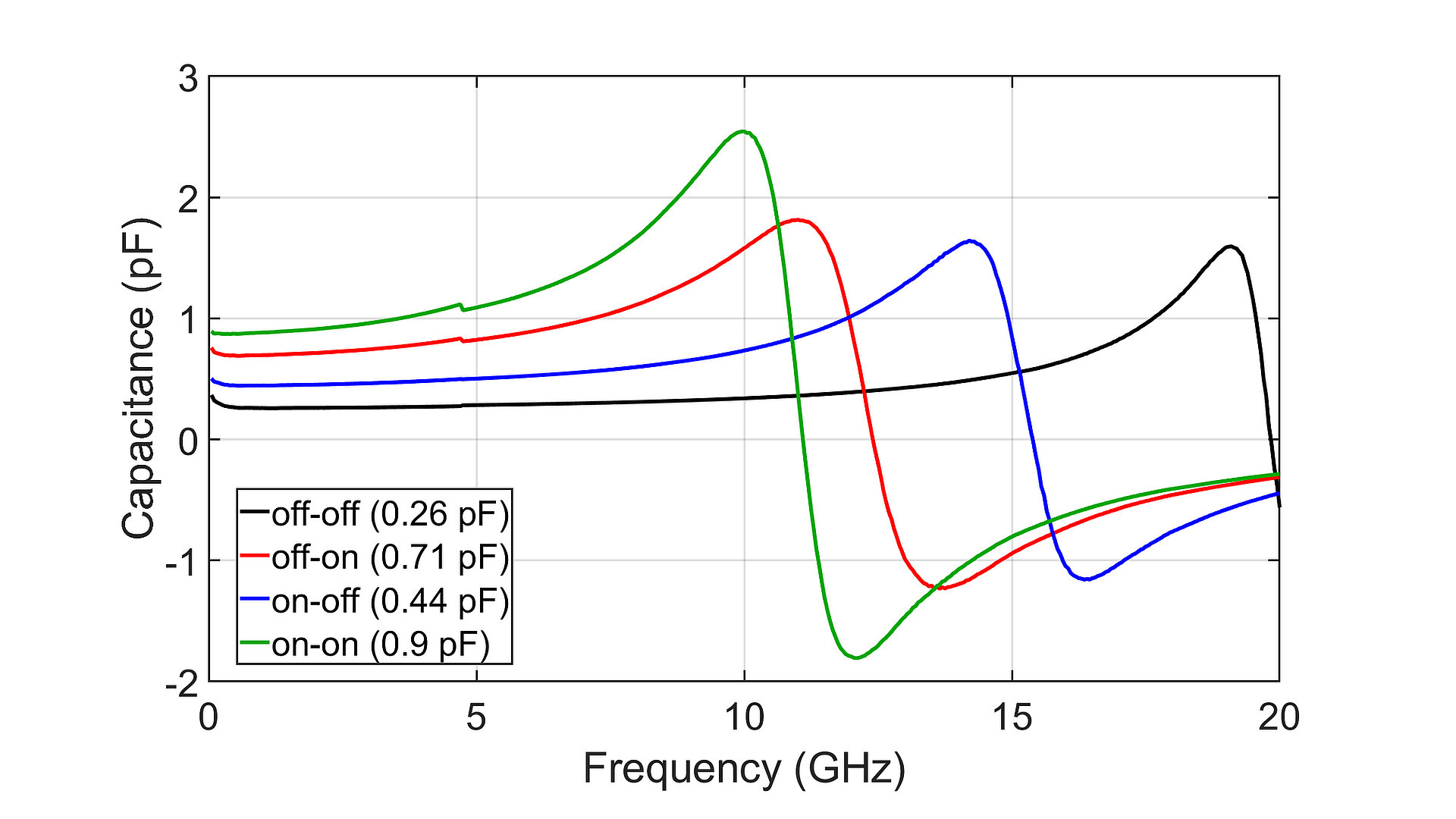
Fig. 3. Extracted capacitance values of the reconfigurable capacitor cell for all four possible states.
There is an increasing need for more complex, high-performance radio frequency (RF) microwave integrated circuits, such as transceivers for telecommunications and radar systems. Circuits that can operate in several distinct frequency bands enable flexible, cost-efficient, and compact solutions. To achieve this, reconfigurable or tunable components can be inserted inside the circuits to change their behavior while adding as little power consumption and chip area as possible.
At FBH, we developed a digitally reconfigurable capacitor cell which combines the reconfigurable elements (capacitors) and the switches (GaN transistors) into a single compact cell. This is realized by placing the capacitors directly between the transistors’ fingers, which considerably reduces the interconnections between the components and thus the occupied chip area.
The full device is composed of two branches, each comprising a transistor switch and a capacitor in series (Fig. 1). By controlling the gate voltage of the transistors, the state of the device can be changed, thus changing the capacitance value seen at the RF port. Four possible states can thus be achieved, providing flexibility depending on the capacitance required, from the smallest value when both transistors are OFF, to the largest when they are both turned ON. To physically connect the components, the two transistor-capacitor branches are connected in parallel via an air bridge (Fig. 2). To maximize integration, each capacitor has been split into two smaller ones connected in parallel. In this example, the top branch integrates a capacitance of 0.15 pF, while the bottom branch provides 0.3 pF, reaching a combined maximum capacitance of 0.9 pF. The total area occupied by the reconfigurable cell is only 127 x 210 µm2, excluding the measurement pads. Its footprint is comparable to that of a fixed capacitor, which makes insertion inside a complex RF circuit almost area-neutral.
The reconfigurable cell is capable of switching between four different states, all with distinct capacitance values (Fig. 3). The capacitance is almost constant up to 5 GHz. Above this frequency, parasitic inductive effects from the metal connections start to degrade the performance. Nevertheless, depending on the selected state, the cell can be used at frequencies up to 15 GHz, which helps greatly in covering different possible bands inside reconfigurable circuits.
Building on these results, we are now focusing on increasing the tuning range above 2 pF and reducing losses altogether by increasing the size of the transistor switches and thus placing bigger capacitors between their fingers. We are also targeting 16 instead of four achievable capacitance states and further reducing the number of connections to increase the frequency of operation. These improvements could enable the capacitor cell to be implemented in a wide range of reconfigurable circuits, increasing their performance and flexibility.
The project was funded by the German Federal Ministry for Economic Affairs and Energy (BMWE) through the Project DigiRad. The work was partly funded by the German Federal Ministry of Research, Technology and Space (BMFTR) under the project reference FMD02 (Forschungsfabrik Mikroelektronik Deutschland).
Publication
A. Chillico, S. Paul, B. Janke, S. Chevtchenko, W. Heinrich, P. Scheele, O. Bengtsson, “A Digitally Reconfigurable Shunt Capacitance in RF GaN Technology Based on Inter-Finger Capacitors,” 20th European Microwave Integrated Circuits Conference (EuMIC), Utrecht, Netherlands, 2025.